2020-10 upd: we reached the first fundraising goal and rented a server in Hetzner for development! Thank you for donating !
Attention! Current pages describe CBSD version 13.0.x. If you are using an older version, please update first.
Attention! I apologize for the automatic translation of this text. You can improve it by sending me a more correct version of the text or fix html pages via GITHUB repository.
FreeBSD clustering: VPC with CBSD
Introduction
The CBSD project is an attempt to combine the most diverse technologies available in the FreeBSD OS in the field of virtualization and containerization, to create a hybrid platform for running isolated environments (in other words: create your own self-hosted AWS without resorting to Amazon ;-). We have already demonstrated FreeBSD technologies such as jail, XEN and bhyve hypervisors. CBSD associates them with components such as RACCT, RCTL, the ability to use network file systems NFSv4/GlusterFS and P9, SR-IOV, CARP, PXE Boot, cloud-init support, etcupdate, vale(4) virtual switches and so on.
The project develops not only user-frendly UI in the form of bsdconfig/dialog-based interfaces and command line, but also WEB interface and API. All these volumes of work, in turn, help other people save time and quickly implement various projects, such as BITBSD and BitCloud.sh: programmable VPS platform for blockchain. Starting as classic wrapper scripts for creating primitive container actions, CBSD eventually got more and more layers of abstractions and expanded its capabilities.
This article will focus on the next big layer in CBSD, which combines the creation of private networks using vxlan technology to create a full-mesh full-mesh network between multiple physical hosts in different parts of the globe. This is one of the biggest challenges in our ambitious RoadMap called Stretched virtual L2 network (vxlan, qinq) for mutliple DataCenter. In turn, this step opens the door to solving the following large tasks as a distributed VALE switch/MAC learning (SDN components), shared-nothing clusters and the implementation of full-fledged DRS/HA, bringing users close to SDDC. We'll talk about this later, starting a series of articles on FreeBSD clustering.
So, a stretched L2 between different hosts helps you organize interconnected virtual networks over classic Ethernet. Having several independent server connections in different parts of the world and with different providers, you can place virtual environments with direct access in them, which will allow you to solve various interesting problems, such as lack of resources at one point or organization of fault tolerance at the DataCenter level.
The Virtual eXtensible Local Area Network (VXLAN) implementation was added to FreeBSD over 6 years ago (at the time of this writing) and has been available since version 8-CURRENT. Using this technology, you can create a large number (16 million) of virtual Ethernet segments via UDP/IP transport or multicast. In point-to-point mode, the setup and operation of the system resembles gif/gre tunnels.Build the VXLAN network
In our example, we have three servers with direct access to each other via the Internet. This number of servers is only a limitation of the author of the article. Each server has only one external IP address. Our task is to combine all three servers into one cluster, inside which we can create isolated virtual networks and environments inside.
In the foreseeable future and with the further spread of IPv6 over the last miles, the implementation of such SDN-based solutions for the needs of small hosting will appear more and more often when you just need to combine your home computer with, say, a friend's home computer in another part of the world and by doing this, both of you will receive fault-tolerant cheap hosting without resorting to the services of data centers.
In the first VPC implementation (v12.1.10), CBSD can only use VXLAN-based network virtualization technology, but in the future we plan to expand the number of such technologies. We will leave an example of vxlan multicast for another more suitable article, in which we will demonstrate a more complex implementation, since in our case the nodes are initially located in different data centers from each other and, in essence, they will create a full-mesh network, network topology, when each node connects to all at the same time.
The hosts in our example and their addresses (IPv4 should also work):
- jhoster1 ( IPv6: 2a05:3580:d800:20f7::1, SkyNET ISP )
- gold-hoster-01 ( 2a01:4f8:241:500c::1, Hetzner DC )
- gold-hoster-02 ( 2a01:4f8:241:500b::1, Hetzner DC )
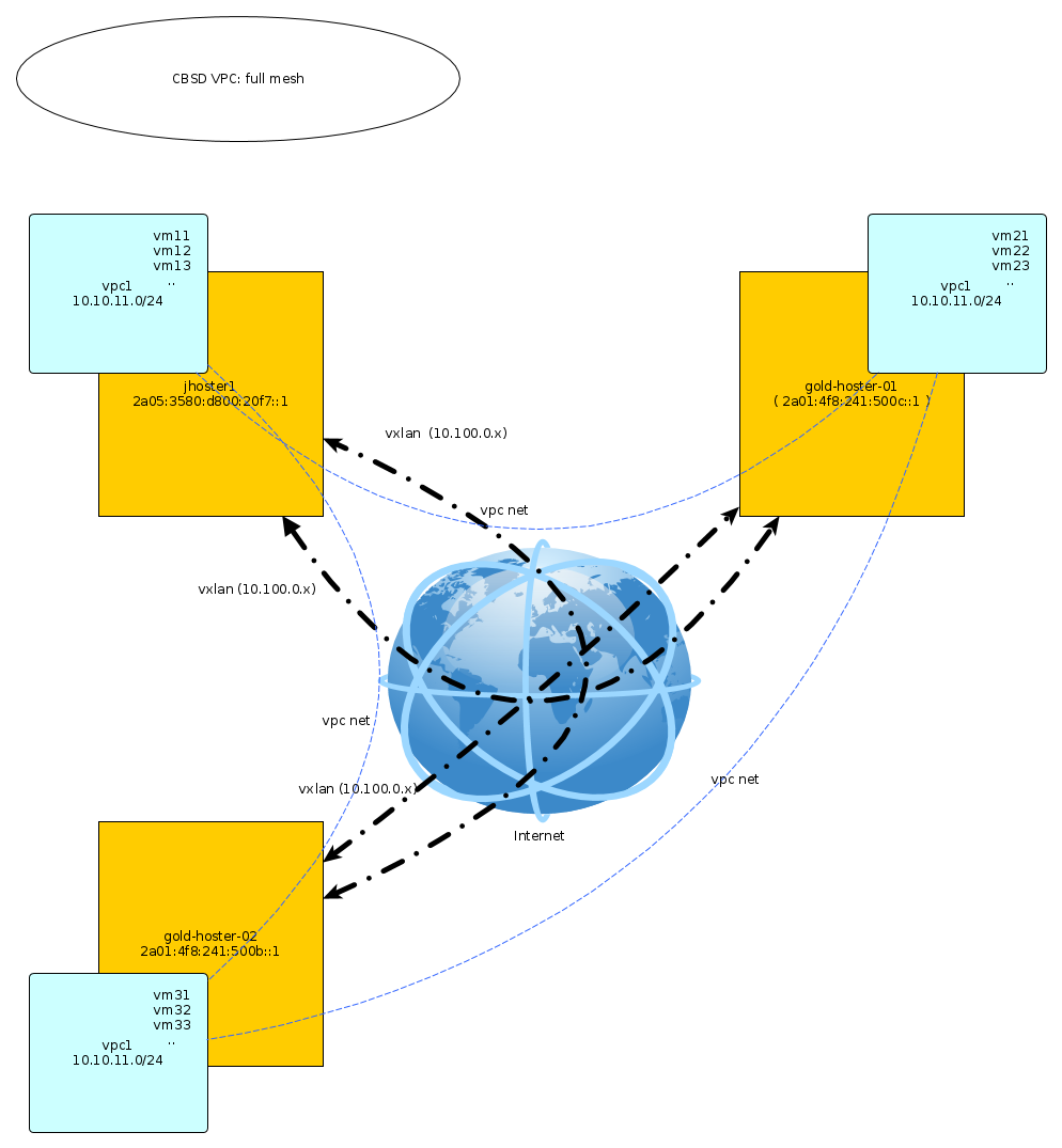
Let's create a VPC in it with the name vpc1 and a working network 10.10.11.0/24 (you can use any). This network of your virtual environments. To build VXLAN tunnels, we also need a separate private network to establish peer-to-peer connections, virtual tunnel endpoint (VTEPs). CBSD can control the initialization and assignment of these addresses automatically. As nodes are added or removed, tunnels will be established or removed dynamically.
Creating a cluster in CBSD begins by adding and exchanging SSH keys between all participants. Prior to the initialization of a multi-node cluster, each node sees only its local environment. Reset the cbsd user password - we need to know it to initialize the cluster. After adding all nodes, the password can be changed or locked - this will not affect the cluster, since further operations will be performed on the remote nodes using the generated ED25519 SSH key.
Run the cbsd node mode=add command on each node, adding the cluster members:
jhoster1:
% cbsd node mode=add node=2a01:4f8:241:500c::1
% cbsd node mode=add node=2a01:4f8:241:500b::1
gold-hoster1:
% cbsd node mode=add node=2a05:3580:d800:20f7::1
% cbsd node mode=add node=2a01:4f8:241:500b::1
gold-hoster:
% cbsd node mode=add node=2a01:4f8:241:500c::1
% cbsd node mode=add node=2a05:3580:d800:20f7::1
At this point, CBSD uses ssh to set up a peer-to-peer network in which teams on the same host can control the environment of neighboring nodes, so be careful with the remove command.
You can initialize VPC for the entire cluster using the vpc mode=deploy command, however we will perform all the composite operations sequentially on each node so that you have an idea of what is going on. The only exception is the mode=sync command, which massively synchronizes VPC settings on nodes.
Creating a VPC begins by inventing a name, for example, let it be called vpc1. In addition to the name, for initialization we need to specify a peer-to-peer network, as well as identify the participants in the VPC. The list of nodes can be specified with a comma in the argument node_member=. If VPC needs to be initialized on all CBSD hosts in the cluster, you can use the reserved “all” value as node_member. Let's do it on all three nodes:
jhoster1:
% cbsd vpc mode=init node_member=all peer_network=10.100.0.0/24 vpc_name=vpc1
gold-hoster1:
% cbsd vpc mode=init node_member=all peer_network=10.100.0.0/24 vpc_name=vpc1
gold-hoster:
% cbsd vpc mode=init node_member=all peer_network=10.100.0.0/24 vpc_name=vpc1
The following mode=init_peers command initializes the configuration and selects the tunnel IP address (VTEPs) for each peer in sequence. This initialization needs to be performed on only one node, after which you can use the cbsd vpc mode=sync command to transfer the initialization result to the rest of the cluster:
jhoster1:
% cbsd vpc vpc_name=vpc1 mode=init_peers
% cbsd vpc vpc_name=vpc1 mode=sync
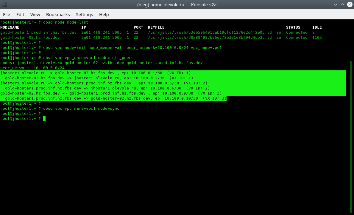
In the output of cbsd vpc mode=init_peers, we see a preliminary map of the distribution of IP addresses between peers. It is this map that we should see in a few seconds in the form of initialized vxlan interfaces with the ifconfig command.
The following command applies the configuration, creating on the node where it is executed, creating and configuring vxlan interfaces:
jhoster1:
% cbsd vpc vpc_name=vpc1 mode=init_vxlan
gold-hoster1:
% cbsd vpc vpc_name=vpc1 mode=init_vxlan
gold-hoster:
% cbsd vpc vpc_name=vpc1 mode=init_vxlan
Run the ifconfig command and make sure that on each server we have N-1 number of tunnels and the remote hosts respond to us by running the ping command:
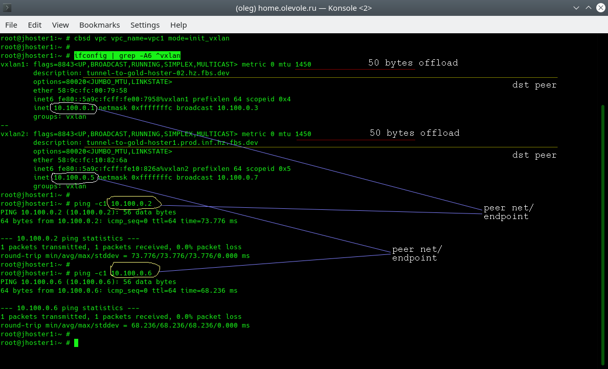
In the output, we see a lower MTU on the vxlan interface - encapsulation adds 50 bytes to each packet. Information about where this tunnel leads to is stored in the description field of each interface. And finally, after vxlan initialization, we can immediately begin to exchange traffic with a remote point.
The last brick in building our isolated network is the creation and integration into it of a VPC-bridge from the created vxlan tunnels.
jhoster1:
% cbsd vpc vpc_name=vpc1 mode=init_bridge
gold-hoster1:
% cbsd vpc vpc_name=vpc1 mode=init_bridge
gold-hoster:
% cbsd vpc vpc_name=vpc1 mode=init_bridge
Please note that if you want to use the IP address at bridge to routing through it containers and virtual machines, address maybe the initializer via additional parameter bridge_ips, for example: cbsd vpc vpc_name=vpc1 mot=init_bridge bridge_ips=10.0.1.1/24
It's all! Now vpc1 with the same settings exists and is available for use as the parent interface for vnet/VIMAGE-based containers and/or virtual network cards for bhyve virtual machines. We just have to check it out:
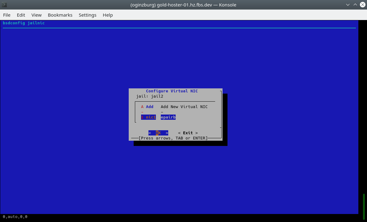
% cbsd jcreate jname=jail1 ip4_addr=0 interface=vpc1 vnet=1 runasap=1
or using cbsd bsdconfig-tui:
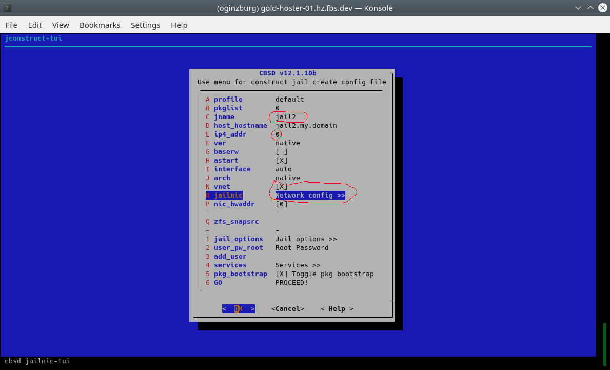
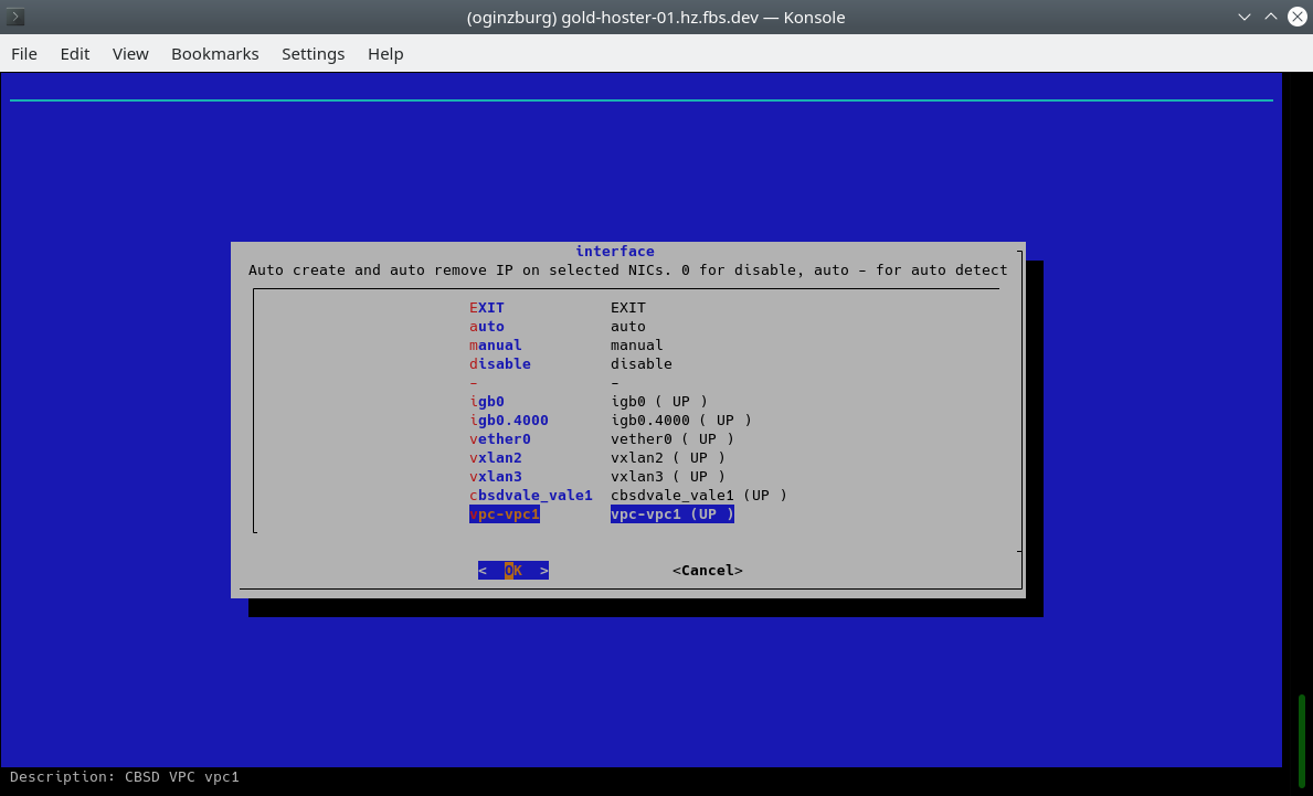
In the menu we need an element to indicate the name of the container, also set ip4_addr to 0, activate vnet (virtualized stack) and select vpc1 as the interface for epair(4):
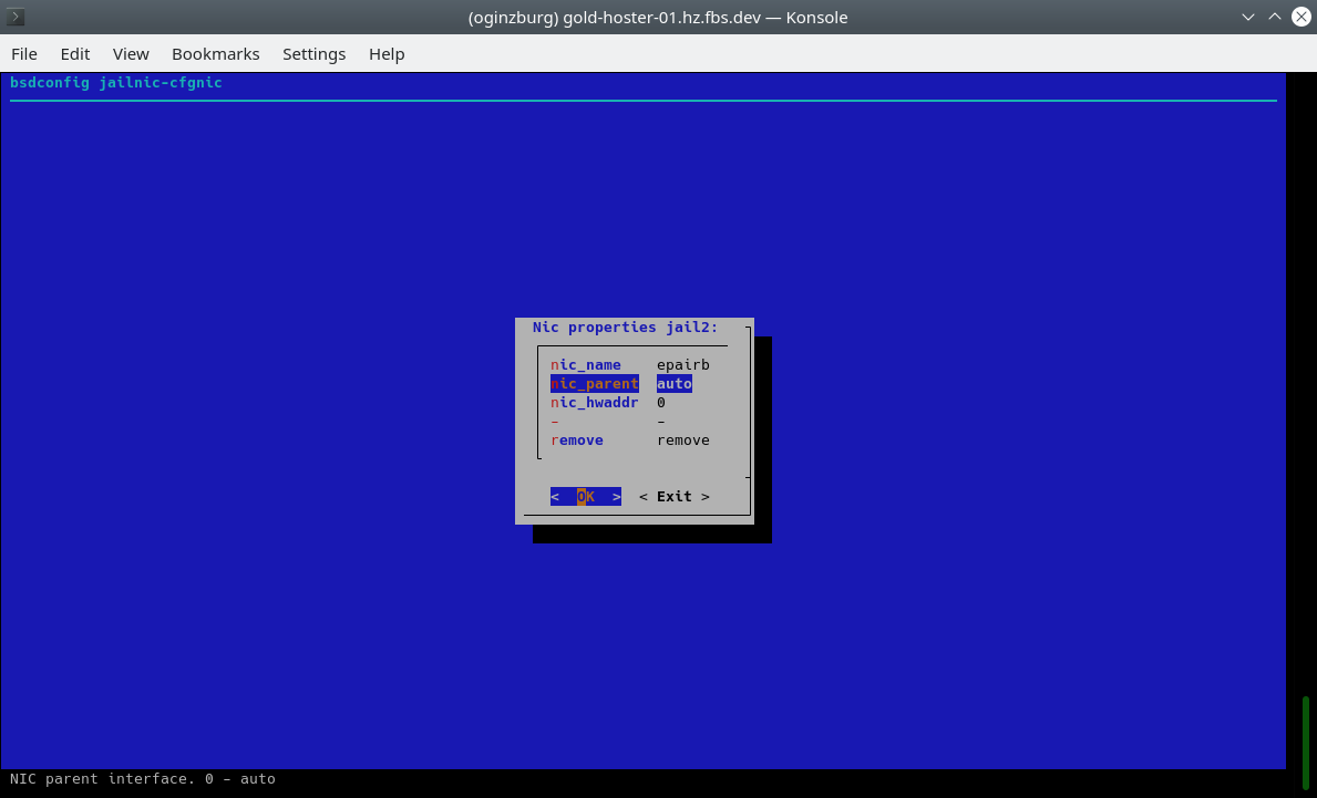
When containers start, we can see the initialization of the epair(4) interfaces and their assignment to our vpc1. From this moment they are isolated in the network segment from any other devices and networks.
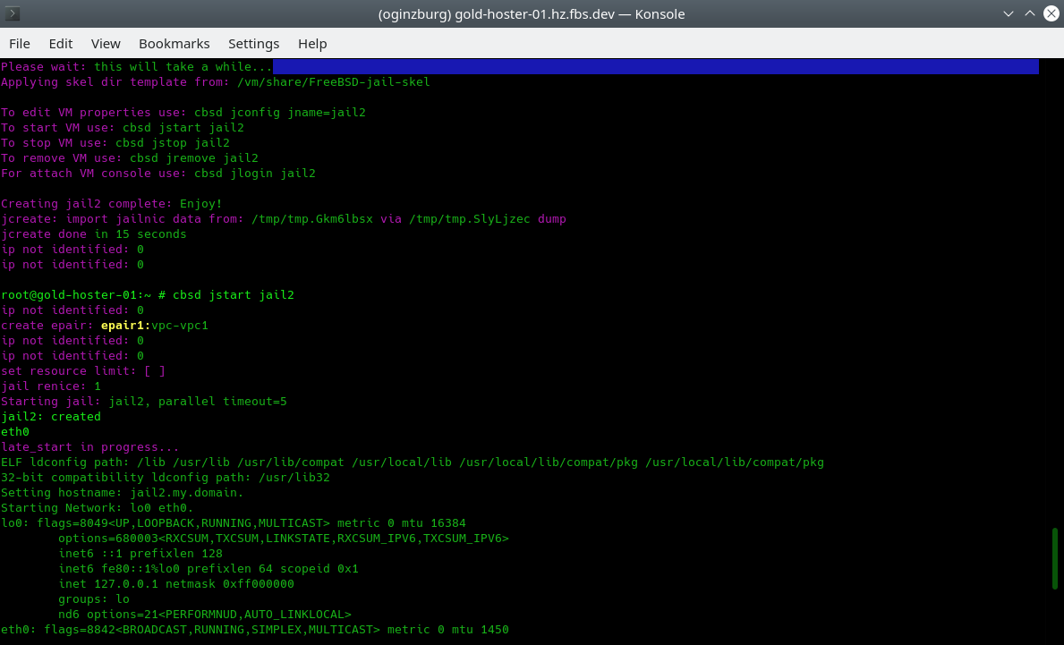
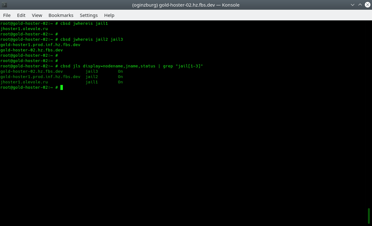
Currently, we have created one container for each of the three physical servers, you can use the jwhereis and jls commands to localize the placement of containers:
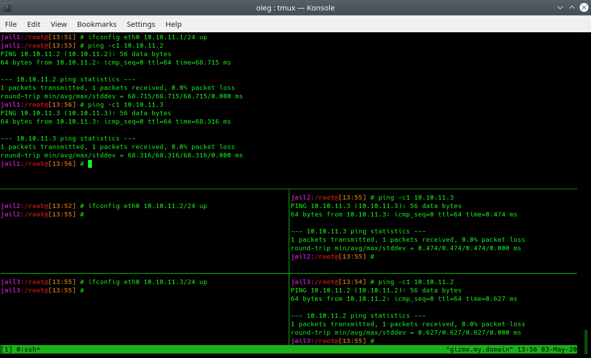
Now initialize the IP addresses inside each container in the classic way via ifconfig. Since the containers are combined into one L2 network, we can assign any network. In this example, we use the network 10.10.11.0/24. We can make sure that all containers see each other:
Init VPC on boot
In order for vxlan/bridge and settings to be initialized when the host is restarted, you can use the generation of FreeBSD rc.d scripts that you need to activate via /etc/rc.conf:
% cbsd vpc mode=init_rc vpc_name=vpc1
With this command, in /usr/local/etc/rc.d/ the cbsd-vpc-vpc1 script will be created, which will raise the entire configuration when you start the server.
conclusion
Using a distributed L2 network between independent data centers and servers, opens up new possibilities for creating distributed, scalable and fault-tolerant services at the data center and region level. If a failure occurs in one region for various reasons, thanks to a single network, you can deploy services anywhere else without worrying about changing addresses, the internal network, and changing application endpoints. In a virtual network, you can have not only a vnet-based container, but virtual machines with any OS supported by bhyve.
See this youtube link for a VPC with jail and bhyve on a practical example. this youtube link, which demonstrates VPC with jail and bhyve on a practical example.